GeoSim Realistic Video Simulation via Geometry-Aware Composition for Self-Driving
[3d-object-detection cvpr differetial-render deep-learning synthetic 2021 lidar autonomous-driving best-paper GeoSim: Realistic Video Simulation via Geometry-Aware Composition for Self-Driving is paper from Uber ATG and was accepted for CVPR 2021 Oral and best paper candidate. This paper proposes a method of rendering videos which is realistic not in image quality but also in physical feasibilty.
To achieve this, this paper makes the following contributions:
- build a diverse bank of 3D objects with both realistic geometry and appearance from sensor data;
- a method of finding the 3D objects which best fits (appearce, location, orientation and motion) into current scene;
- image-based rendering to properly handle occlusions, and neural network-based image in-painting to ensure the inserted object seamlessly blends in by filling holes, adjusting color inconsistencies due to lighting changes, and removing sharp boundaries.
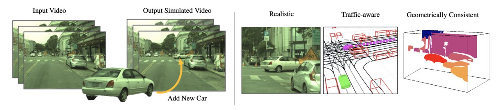
The proposed method could be visualized as figure above.
Realistic 3D Assets Creation
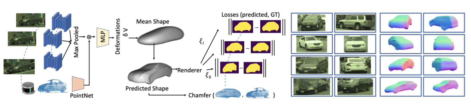
The paper proposes a method of build a diverse set of 3D objects from a dataset of video data and LIDAR scan. 3D bounding box labeled for the object in the thing is required. The method is visualized above.
The i-th object is represented by its 3D shape \(V_i, F_j\) (vertices and faces), appearance \(I_{i,j}\) and silhouette \(S_{i,j}\) (a binary mask), where \(j\) is the view angle. Our backbone consists of two submodules. A convolutional network takes each cropped camera image as input and outputs a corresponding feature map. The feature maps from multiple cameras are then aggregated into a one-dimensional latent representation using maxpooling. For shap representation, instead of relying on PCA basis, it parameterizes the 3D shape as a category-specific canonical mean shape with per-vertex deformation.
The network is trained in self-supervised way, especially:
- The silhouette loss measures the consistency between the 2D silhouette (automatically generated using the state-of-the-art object segmentation method PointRend [40]) and the silhouette of the rendered 3D shap. It is based l2 loss;
- The LiDAR loss represents the consistency between the accumulated LiDAR point cloud and the mesh vertices, defined as the asymmetric Chamfer distance.
- a Laplacian regularization which preserves local geometry and prevents intersecting faces;
- mesh normal regularization which enforces smoothness of local surfaces;
- edge regularization which penalizes long edges. Please refer to supp. material for details.
The dataset contains ~8000 vehicles.
Object Placement
To render the scene, the first step is add new objects to the scene, which includes selection of object, locations, positions and motions. It should be consistent with the scene. The approach takes as input camera video footage, LiDAR point clouds, and an HD map in the form of a lane graph and automatically outputs a video with novel objects inserted into the scene.
To this end, the following steps are taken:
- we first infer the location of all objects in the scene by performing 3D object detection and tracking;
- For each new object to be inserted we select where to place it (2D location and 1D orientation). We reject all samples that result in collision with other actors or background objects;
- we propose to retrieve objects from the asset bank that were viewed with similar viewpoints and distance to the camera in the original footage;
- We then utilize an intelligent traffic model for our newly placed object such that its motion is realistic, takes into account the interactions with other actors and avoids collision;
- The output of this process defines the new scenario to be rendered.
Scene Rendering
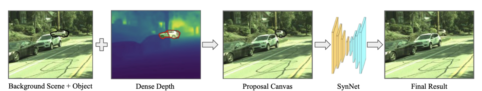
Given the new scenario, we could do rendering, which involves the following three steps (as visualized above)
- Utilize the asset’s 3D shape to warp the source to the novel target view;
- We use a novel-view rendering with 3D occlusion reasoning w.r.t. all elements in the scene, to create the appearance of the novel objects in the new image;
- shadown reasoning: we render the scene with and without the inserted objects, and add the shadow by blending in the background image intensities with the ratio of the two rendered images intensities;
- occlusion reasoning: compute by evaluating for each object pixel if the target image’s depth is smaller than the corresponding object pixel’s depth;
- Finally, we utilize a neural network to fill in the boundary of the inserted objects, create any missing texture and handle inconsistent lighting.
Experiment Result
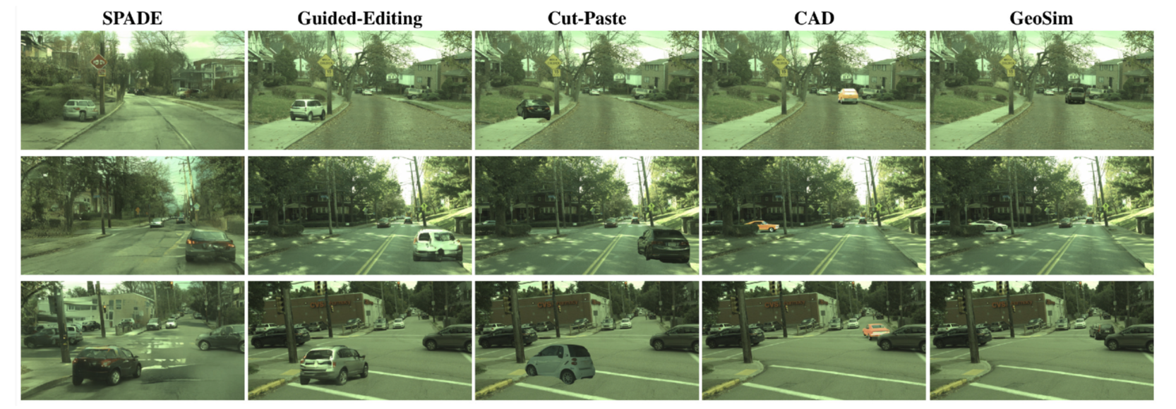
The proposed method is evaluated on several other method, including CAD, as shown below. Obviously, SPADE, Guided-Editing and Cut-Paste could be guarantee the new object is placed in physic meaningful locations; the rendering is not realstic enough.
CAD method in the other creates very good result, it requires not only creating 3D CAD model for the new object but also manual placement of new objects.